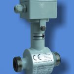
Transmitter can be integral part of the sensor – compact version or it is connected with the sensor with a cable – remote version.
Technical parameters
| Nominal diameter | DN15..DN150 |
|---|---|
| Nominal pressure | PN6, PN10, PN16, PN25 |
| Thread | Pipe Thread DIN ISO 228/1 |
| Electrode material | Stainless steel AISI 316 Ti, Hastelloy C-276, Ti, Pt |
| Lining | Special rubber (NG), PTFE (T), PVDF (PV) for DN4 ÷ DN8 |
| Liquid temperature | 0 - 90°C (NG), 0 - 150°C |
| Protection | IP67, IP68 |
| Installation | Compact or remote version |
Installation lengths
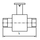
In the following table are stated the standard installation lengths of the sensors for all manufactured dimensions and linings. On special request, we can manufacture sensors with other installation length according to the customer’s requirements.
| DN | ISO 13359, EN 14154 | Optional | Scheme |
|---|---|---|---|
| 4 - 6 | 160 | ||
| 15, 20 | 200 | 150 |  |
| 25 - 80 | 200 | 215 | |
| 100 | 250 | 215 | |
| 125 | 250 | 305 | |
| 150 | 300 | 305 |
Range limits
Selected sensor range has to be in the flow velocity interval 0,1 up to 12 m/s. Volume flow rate limits for the single dimensions are shown in the table. It is suitable to choose the operational sensor range between 0,5 and 5 m/s.
| DN | Flow rate l/s | Flow rate m³/h | |||
|---|---|---|---|---|---|
| mm | inch | Qmin | Qmax | Qmin | Qmax |
| 4 | 1/6" | 0.0013 | 0.1508 | 0.0045 | 0.5429 |
| 6 | 1/4" | 0.0028 | 0.3393 | 0.0102 | 1.2215 |
| 8 | 1/3" | 0.0050 | 0.6032 | 0.0181 | 2.1715 |
| 15 | 1/2′ | 0.0176 | 2.120 | 0.0636 | 7.634 |
| 20 | 3/4′ | 0.0314 | 3.769 | 0.1130 | 13.57 |
| 25 | 1′ | 0.0490 | 5.890 | 0.1767 | 21.20 |
| 32 | 1 1/4′ | 0.0804 | 9.650 | 0.2895 | 34.74 |
| 40 | 1 1/2′ | 0.1256 | 15.07 | 0.4523 | 54.28 |
| 50 | 2′ | 0.1963 | 23.56 | 0.7068 | 84.82 |
| 65 | 2 1/2′ | 0.3318 | 39.81 | 1.194 | 143.3 |
| 80 | 3′ | 0.5026 | 60.31 | 1.809 | 217.1 |
| 100 | 4′ | 0.7853 | 94.24 | 2.827 | 339.2 |
| 125 | 5′ | 1.227 | 147.2 | 4.417 | 530.1 |
| 150 | 6′ | 1.767 | 212.0 | 6.361 | 763.4 |
Attached files
- FLOMAG 3000 Datasheet EN [504 kB]
- FLOMAG3000 Manual EN [1275 kB]


